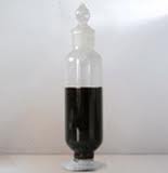
Motor oil, or engine oil, is an oil used for lubrication of various internal combustion engines. While the main function is to lubricate moving parts, motor oil also cleans, inhibits corrosion, improves sealing, and cools the engine by carrying heat away from moving parts.
Ashless Machine Oil
Machine oils designed to help reduce maintenance costs and increase equipment uptime. Formulated with advanced ashless additive technology and high quality base oils, machine oils meets major bearing and paper machine builder specifications
Green Lubricants
Truly green lubricants are those that optimise energy efficiency and minimise wear in the machinery which they lubricate and which have maximised service lifetimes in order to reduce the amount of lubricant required.
Environment Friendly Lubricants
For example, consider a lubricant that will be 100 percent degraded in 28 days. Is it still environmentally friendly if it is toxic and destroys or alters a significant portion of plant or animal life during the degradation process?
The power of an engine
The power of an engine may be measured or estimated at several points in the transmission of the power from its generation to its application. A number of names are used for the power developed at various stages in this process, but none is a clear indicator of either the measurement system or definition used.
Good day! As an ISO certified factory, we specialized manufacture Mould making/ Sheet metal process/ Die-casting/ Precision stamping/ Machining parts, with strong competitive price and excellent quality, for more than 20 years. Any questions and enquiries will be highly regarded. Just email us the drawing and detailed requirement, you will get a complete quotation with technical analysis within 24 hours.
Your prompt reply is highly appreciated.
Best regards sincerely!
Michael ________________________________________ Shenzhen, China
来自 RE:Look forward to your reply / Account Manager/iyrg4d/ 的消息:
Dear Sir/Ms,
Good day! As an ISO certified factory, we specialized manufacture Mould making/ Sheet metal process/ Die-casting/ Precision stamping/ Machining parts, with strong competitive price and excellent quality, for more than 20 years. Any questions and enquiries will be highly regarded. Just email us the drawing and detailed requirement, you will get a complete quotation with technical analysis within 24 hours.
Your prompt reply is highly appreciated.
Best regards sincerely!
Michael ________________________________________ Shenzhen, China
A process for making an ashless hydraulic fluid or paper machine oil comprising,
a) hydroisomerization dewaxing,
b) fractionating,
c) selecting a fraction having a very high VI, and a high level of molecules with cycloparaffinic functionality,
d) blending the fraction with an ashless antioxidant.
A process for making ashless paper machine oil, comprising:
a. selecting two lubricating base oils both having a consecutive number of carbon atoms, greater than 35 wt % total molecules with cycloparaffinic functionality, and a viscosity index greater than 150;
b. blending the two lubricating base oils with an ashless antioxidant additive concentrate and no viscosity index improver to make an ashless paper machine oil; wherein the ashless paper machine oil has a result of greater than 680 minutes in the rotary pressure vessel oxidation test.
It is widely accepted that oil contamination is one of the major causes of component failure. When practicing proactive maintenance, it therefore makes sense to give oil cleanliness a high priority. By maintaining a high level of oil cleanliness, effects such as machinery failure, resultant downtime and expensive repair costs can be kept to a minimum.
There are many factors to consider when cleaning up your act. The first and most important place to start is at the source: the new oil. Oil could be contaminated when it leaves the refinery, during transportation or during the transfer to the end-user's or vendor's tanks. But more often than not, it is the manner in which the oil is stored by the user that results in new oil contamination.
Oil Storage
Oil storage is an important factor to consider when implementing proactive maintenance, but it is usually at the bottom of the list of priorities or overlooked completely. Many times, the area and manner in which the oil is stored can introduce contamination. So how do you ensure that this does not happen? Let's take a closer look at proper oil storage conditions.
The most common oil container used by the oil industry is the 210-liter (55.5-gallon) drum. Filled with oil, it weighs approximately 220 kilograms (485 pounds). These drums should be handled carefully to prevent damage to the drums, causing them to puncture or burst. Containers should be moved immediately to a storage area and remain sealed until needed. Oil drums or containers should be stored indoors whenever possible.
To avoid contamination when storing oil outdoors:
Do not store the drums outside indefinitely, because drums can rust and
contaminate oil.
Ensure bungs are tight and that drum seams do not deteriorate. This can occur
because temperature changes lead to expansion and contraction of the metal,
causing oil leaks or contamination.
Keep drums or containers as dry as possible and away from water. Do not allow
water to accumulate on any part of the container. This water can be drawn into
the container when changing temperatures cause pressure changes within the drum
or container.
Store the drums under a roof, a lean-to or cover with a tarp.
Before removing bungs, dry and clean around the bung areas to prevent
contamination with dirt and water - the two most common and destructive
contaminants in any environment.
Lay the drums on their sides, on a specially constructed rack if possible. Make
sure that the bungs are in the 3 o'clock and 9 o'clock positions. This generally
ensures that the content of the drum is above the bung level. This minimizes
water (and dirt) entry and stops the seal from drying out. If drums must be
stored upright without any protection from the elements, tilt them slightly and
make sure the tilt is parallel to the 3 o'clock/9 o'clock bung line. This
prevents water from collecting around the bungs.
When storing oil containers or drums indoors, remember the following tips:
The storage area should be a cool, dry area free from extreme temperatures.
Keep the storage area clean at all times, with a formal cleaning schedule in
place.
Minimize the presence of any contaminants. Contaminants could result from
manufacturing processes, the environment, etc.
Oils can also be stored in bulk storage tanks. It is often easier to maintain low particulate contamination levels when oils are stored in bulk tanks because they are normally closed to the atmosphere and the oil is dispensed via a pump or tap. Ensure the seals are intact and fitted with desiccant (recommended) breathers.
Oil Dispensing
Contamination due to dirty top-up containers or dispensing equipment is a common problem. As with most of the points raised with storage, hygiene and common sense are what count. Dispensing equipment should be kept clean to minimize contamination of the oil. Keep in mind these few points:
Make sure pumps and portable lines are kept clean and are stored in a clean
environment.
Avoid topping up and filling in exposed areas.
If top-up containers must be used, make sure they are clean and not left open to
the elements. Avoid mixing different oils in these containers.
Quick-coupling fillers will ensure that environmental contaminants do not enter
lubrication systems.
A number of companies produce utility cans for topping-up purposes. These have
lid and spout designs that keep contaminants out, and some have a pressurized
dispenser.
Clean around filler caps before removing.
Make sure the tops of drums are clean and free from dirt and water before opening.
Once sufficient oil storage has been established, the next place for oil particulate contamination to occur is once the oil is in the machine or component. This can happen in many ways. Open vents provide an easy means for dirt to enter machines. Faulty breathers are a common source of particulate contamination. Oil leaks or damaged seals are also culprits. Remember, if oil is able to leak out of a system, contaminants are able to enter the system. Repair damaged seals or oil leaks as soon as possible.
Internal Contamination
Some form of internal particulate contamination is inevitable and can denote a problem with the machine/component. Internal particulate contamination includes any particles that contaminate the oil once it has been placed in the closed lubricated system - for example, wear particles, seal material, etc. When external particulate contamination is under control, a high particle count provides an early warning for an abnormal wear situation developing.
Particles, especially catalytic metal particles like copper, iron and lead, increase the oxidation rate. These particles also strip the oil of its antiwear additives, extreme pressure additives, rust inhibitors and dispersants. Numerous small particles in stable suspension can cause the oil's viscosity to increase and may promote foaming.
These particles are abrasive. As with all particulate contaminants, once in the oil, they accelerate the wear rate dramatically because abrasive wear can cause a chain reaction in lubricated machinery. The typical chain reaction is:
Abrasive wear particles become work hardened.
Work hardened particles produce more particles.
New particles become work hardened.
Chain reaction occurs until the particles are removed by filtration or the
machine fails.
It is, therefore, imperative to monitor oil cleanliness and keep particulate contamination to a minimum. This is accomplished by implementing a contamination control program in these easy steps:
Contamination Prevention
After ensuring oil is free from contamination, consider the times when servicing the machine becomes necessary. When component changes or work is performed on the machine, make sure that all new components are free from contamination and that further contamination does not enter the machine during servicing. Ensure that all seals and breathers remain intact to prevent contaminant entry.
Contamination Removal
Contamination removal is accomplished with filters and filtration systems or oil draining and discarding. Each application must be evaluated when deciding which option is more cost-effective. Using filters to achieve target cleanliness levels does not always require the best or most expensive filter. A cheaper filter used correctly may produce the desired results at a lower cost. The effectiveness of a filter or filtration system can be tested by taking representative oil samples from before and after the filter.
Monitoring Cleanliness Levels
For effective monitoring of the oil, check for cleanliness levels in the machine as well as at several other points, such as new oil sources, bulk tanks or stored lubricants, or oil in service in equipment.
To monitor the level of contamination, test the oil and obtain a particle count. Different instruments using different methods are available to test particle count. Wearcheck uses the most common type of automatic particle counter, which operates on a light blockage principle. In this particle count test, the total number of particles, irrespective of origin, are counted in a number of sizes, ranging from greater than 5 to 100 microns.
The results are expressed as the total number of particles per milliliter of oil in the various specified size ranges. A cleanliness rating is also reported. The cleanliness rating is expressed as a two-number code X/Y, where X represents the total number of particles per ml greater than 5 microns and Y represents the total number of particles per ml greater than 15 microns.
Target Cleanliness Levels
For warranty purposes, certain manufacturers have established maximum cleanliness ratings for their equipment. It is, therefore, difficult to know what the optimum cleanliness level is for your machines. Each machinery class has an appropriate oil cleanliness level for that application. In general, machines with tight clearances benefit greatly from clean oil.
It takes time to monitor results and choose an exact level if you haven't been given one by the manufacturer. Be realistic and consider what is cost-effective when setting target cleanliness levels. It makes no sense to expect such high cleanliness levels that you spend more money discarding or filtering your oil than it would cost to replace the machine in the event of a failure.
Sampling technique is of utmost importance when monitoring cleanliness levels. Sometimes an oil may have a high particle count result, but the actual oil in the machine is perfectly clean. This could be the result of two scenarios:
First Scenario
Ensure that the oil sample taken is representative of the oil in the machine. The oil should be well mixed when the sample is taken and no external contamination should be introduced during sampling. This external contamination could result from factors such as:
A dusty environment
A manufacturing process that produces particulate contamination
The oil not being well mixed and sediment from the tank bottom draining into the
oil sample bottle
A dirty sample valve
Dirty sampling equipment, especially when samples are transferred from another
sampling container
Sample bottle caps not being replaced immediately after the sample is taken
Dirty sample bottles
Second Scenario
Consider the laboratory method to obtain particle count data. Wearcheck operates an optical particle counter using the light blockage technique. This involves passing a laser beam through a controlled stream of oil, measuring the amount of light blocked by individual particles as they pass through the beam. Obviously, larger particles block more light than smaller ones, making size information relatively easy to obtain.
This method is sensitive and has some limitations. Particle count data is inflated by the presence of water droplets or gas bubbles in the sample because these are seen as particles. The laser cannot pass through dark or extremely contaminated samples, making them impossible to measure.
It is important to look at the appearance of the oil as well as other laboratory tests, such as water concentration and any comments based upon a microscopic examination, before reacting to an abnormal particle count result. It is also important to ensure that the sample is taken in the same manner and from the same sampling point each time a piece of equipment is sampled.
This consistency allows samples to be compared with confidence (compare apples to apples). Randomly sampling a machine from up and downstream of a filter can produce a confusing set of laboratory results if no sampling point information is included with the sample.
To summarize, set target cleanliness levels, achieve target cleanliness levels with continuous exclusion and removal of contaminants, and monitor contamination levels regularly to assure conformance to standards.
Benefits
Better lubrication leads to increased profits. Lubricants free from contamination provide better service to machines. Properly lubricated machines will provide better, more reliable and profitable service to the owner or operator. Why then is contamination control given such a low priority in most proactive maintenance programs?
This is largely due to a lack of understanding of contamination, its consequences and how to control it. Proactive maintenance requires a long-term investment in machines and people. A small amount of particulate contamination in a machine may not lead to an instant failure or halt operation today, but it will invariably shorten the machine's life. When the machine finally fails, it is difficult to determine or even prove loss of life due to particulate contamination.
Education is the most important step on a journey of successful contamination control. All personnel must be educated about their roles in the process and the benefits of reaching the destination. Teamwork is imperative and an educated, dedicated team will create an efficient, cost-saving contamination control program. The rule of thumb is that it costs 10 times as much to remove the particulate contamination than to prevent it from occurring in the first place.
The bottom line is this: Clean up your act and you will achieve greater machine availability and utilization. Reduced operating costs and increased profits will follow naturally.
For a complete and proper lubrication program to work effectively and provide the most return on investment, the entire gamut of lubrication must be considered, ranging from receiving to application.
Through this gamut there are missed opportunities to increase equipment productivity and reliability and to maximize the returns of investing in a professionally designed lubrication program. One of the biggest and most costly missed opportunities is proper lubricant storage and handling.
Many facilities are unaware of the danger improper lubricant storage and handling practices create and what inevitable fate it can lead to in terms of equipment reliability and life-cycles. Proper lubrication is not only about the right amount-at the right time-at the right place, it is also about keeping lubricants clean, cool and properly identified.
Here are some tips to help outline the best practices for proper lubrication storage and handling:
1. Lube Room Design and Requirements
A properly designed lube room must be functional, safe and expandable, and provide all necessary storage and handling requirements for the facility. Lube room designs should allow the maximum storage capacity without allowing for too much bulk oil and grease storage. Limiting the amount of bulk oil and grease storage will allow the oils that are stored to be used in a timely manner. Some key features to consider are a limited access door, which will allow for logging of who and when a lube technician enters and leaves the room; visible landing area for new lubricants; log all new lubricant deliveries; make filtration of stored lubricants easy; provide proper safety devices; designate enough floor space for fire proof storage cabinets to store top-up containers, grease guns, etc.; and include a desk and computer to track inventory, sampling, filtration, receiving, etc.
It also is a smart idea to have a separate storage area to store bulk totes, drums, buckets, etc.
2. Bulk Oil Storage
The first area of a lubricant storage and handling system that requires attention is bulk storage. Whether storing lubricants in a 10,000-gallon tank or 55-gallon drums, it is very important to ensure the lubricants’ quality is not tainted by contamination or additive settling. To help ensure lubricants stay in an optimal condition, one must determine how much lubricant should be stored at one time.
To aid in this process, certain steps can be employed, such as:
Determine lubricant consumption rate. Consumption will vary greatly depending on industry and equipment type. To ensure the right quantities of lubricants are being stored at a facility, the consumption rate must be determined. There are many factors that contribute to consumption, ranging from leaks to excessive drain and fills.
Determine lubricant storage capacity. The required lubricant storage capacity depends on consumption, but often there are too little or too many lubricants stored at one time. The proper storage capacity should maximize shelf life but allow for a certain percent excess of critical lubricants to be stored for emergency situations.
Determine lubricant supplier turnaround time. A lubricant supplier’s turnaround time should be a metric used to aid in determining the quantity of lubricants stored. If there is a short time interval between deliveries, fewer lubricants can be stored onsite, but if there is a lengthy time interval between deliveries, the quantity of lubricants stored onsite should account for this.
Once the consumption rate and storage capacity have been determined, one should decide what type of storage containers will be used. The correct size storage container is a direct reflection of the consumption rate and storage capacity. If a large consumption rate is determined, a large bulk storage tank may yield the best results, but if a low consumption rate is determined, a rack mounted storage system or 55-gallon drums may yield the best results.
For smaller facilities that have a small consumption rate, the use of drum storage may be the best option.
A large bulk storage area must require the same attention as smaller areas, constructed to ensure the lubricant is not tainted by contamination or additive settling.
3. New Oil Receiving
Oftentimes, improper receiving techniques do nothing but promote higher risks of contamination ingression, mixing of lubricants, etc. Proper written receiving procedures should be in place to ensure the highest level of consistency and cleanliness is maintained. Proper receiving techniques should include filtration of incoming oils. Many times new oils may be dirtier than your defined particle target cleanliness level. Meaning, if you define your particle target cleanliness level and spend time, money, manpower, etc., to achieve these levels of in-service lubricant cleanliness, the last thing you want to do is contaminate it with “dirty” new oils.
4. Quality Control
Quality control of lubricants delivered from lube suppliers must be verified to ensure the correct product is being delivered and that the cleanliness of the delivered lubricant are up to current target particle and moisture cleanliness levels.
To help ensure your lubricants are meeting their standards, the use of oil analysis is a powerful tool and will reveal the following:
Quality of base stocks
Additive quality and concentration
Lubricant performance properties
Thickener performance properties (grease)
Common ways oil can become contaminated
5. Presence of Mixed or Contaminated Lubricants
Oil analysis results and other quality assurance variables, such as damaged containers, rusted containers and any other quality issue, should be well documented and cataloged.
Items to note in the documentation phase are:
Delivery date and date of oil sample taken
Inspection results of storage containers
Labels depicting results of oil analysis test
Itemized checklist for sampling test
Periodic decontamination with filtration
Whichever storage container is chosen, it is best to filter the new oil while filling the storage container. Doing so will reduce the amount of contamination that is delivered with the new oil, but periodic filtration and agitation should be performed to maintain certain ISO cleanliness levels and prevent additive settling. Periodic filtration is a good practice to ensure clean, fresh oil will be used to perform top-ups and drain and fills. There are two primary methods for filtration of bulk stored oils: hard plumbed filtration system or filter cart. The hard plumbed filtration system works best in conjunction with a rack mounted system.
Each container should be fitted with a breather, sight glass, filter, lubricant label, quick connect fittings and dedicated dispensing line. This system will help ensure the lubricants are at optimal condition when they are needed and the right product for the application is dispensed.
Periodic filtration for drum storage also is easy with the use of a filter cart once the drums are equipped with quick couplers. No matter how large or small the storage container, periodic decontamination should be a priority to maintain the quality of the stored lubricant.
6. Dispensing Options for Stored Oils
When stored oil is transferred from the bulk storage system to the top-up container, it is best to filter the dispensing oil. This can be made very easy with the use of a hard plumbed filtration system and a rack mounted storage system fitted with dedicated dispensing nozzles. If using 55-gallon drums, they can be fitted with quick connect fittings, a hand pump, an inline filter manifold breather and sight glass to achieve the same goal.
Improper dispensing of new oils into top-up containers is a primary cause of self-induced contamination. Proper techniques and tools must be used to ensure your new, filtered oil is transferred to the top-up container with minimal exposure to atmospheric conditions. Not using proper techniques here could be a waste of time to the filtration efforts, storage and in-service lubrication cleanliness.
7. Precision Top-Ups and Drain and Fills
Once the bulk storage system is properly set up, one should consider the method for transporting oil and filling machines. The best top-up method utilizes a proper top-up container, one that is sealed from the environment, has a built in spout, hand pump, etc. If short cuts are taken at this stage, all of the time and effort spent building and designing the bulk storage system and ensuring the quality of the bulk oil with filtration will have been wasted. Too many times oil is highly contaminated from the time it is dispensed into the top-up container to the time it is added to the machine.
Using washable and re-usable top-up containers allow for easy cleaning and maintenance. Typically, non-seal-able top-up containers that are re-used introduce large amounts of containment to the system, which could counteract any effort of removing or excluding contaminants, and also can have a slight lubricant cross-contamination effect.
For top-ups of larger sump volumes, such as large gearboxes, circulating system reservoirs, etc., the use of filter carts is the preferred method for transferring the new oil from the storage container to the machine.
8. Proper Top-Up Container and Grease Gun Storage
Storage for top-up containers, grease guns, rags, etc., is another important step to ensure contaminants are not introduced to the lubricants as a result of poor housekeeping. These tools should have their own dedicated fire-proof storage cabinets for easy access and organization.
Grease storage is simpler than oil storage but also must not go overlooked. Open grease tubes and drums are magnets for attracting airborne contaminants such as lint and dust. Securing used grease tubes that will be re-used in seal-able washable containers is considered the best practice. The containers will hold one tube of grease and allow for great contaminant exclusion. Used drums of grease are at an even higher risk of contamination. These drums are often opened and used over a greater period of time, leading to more and more opportunities for contaminants to enter. If not using a sealed air style grease dispensing unit for drums of grease to fill grease guns, some of the best methods for contaminant exclusion are to use Velcro style covers or snap-on caps. Using these types of contaminant exclusion devices will keep the grease cleaner and prolong its life.
Grease guns should be stored in a clean, dry and controlled environment. They are precision tools that must be taken care of in order for them to provide the maximum degree of accuracy and reliability. Grease guns should be regularly cleaned and inspected for proper function and an annual calibration should be performed. This calibration will ensure the same volume of grease is still being dispensed with one shot as when the gun was new. The best method for grease gun calibration is to use a postal scale to measure how much grease is dispensed with one pump.
Lubrication tools should be stored in a fire-proof storage cabinet for easy access and organization.
9. Lifecycles and Lubricant Shelf Life
For both oil and grease, one should be aware of their respective shelf life. Exceeding their OEM shelf life may render the product useless or severely hamper its performance. For this reason it is best to use the First-In, First-Out (FIFO) method. This method simply requires the maintenance professional to use the oldest lubricants that were put into the storage system first and the newest lubricants put into the storage system last. This will help ensure lubricants do not accidentally exceed their recommended shelf life.
As previously mentioned, OEM storage limits should be considered when storing greases and oils. Table 1 outlines maximum storage limits for different grease types and oils.
NLGI recommends the following steps for best practice of grease storage:
Store the grease in a cool, dry indoor area where airborne debris is at
a minimum
Use the oldest container first
Keep containers tightly covered
Wipe off the edges of a container before opening it to avoid intrusion
of dirt
Where necessary, grease should be brought to a satisfactory dispensing
temperature just before being put into service
Clean grease-handling tools (such as spatulas, drum pumps, etc.)
When a container has been partially emptied and the remainder will not
be immediately used, all void spaces within the remaining grease should
be filled with grease, and the surface leveled and smoothed
Store grease cartridges (tubes) vertically with the removable cap up
(ref. NLGI)
Maximum Storage Time
10. Labeling and Identification
Lubricant labeling is one aspect of storage and handling that is often overlooked. Labeling is just as critical as periodic filtration and without proper labeling it is very easy for lubricant cross contamination to occur. Lubricant cross contamination is a result of mixing two lubricants together and can yield a devastating result. This happens more often in the dispensing equipment rather than the bulk storage equipment. A labeling system can be a simple concept but could prove to be difficult to implement and maintain. Decide how to label each corresponding lubricant from bulk storage to the equipment it will be used in. It can be a color coded system, an alphanumeric code system that depicts important performance data about the lubricant, or a combination of both. Any labeling system can efficiently ensure the right lubricant is used at the right location and prevent cross contamination, but in order to do this, the labeling system must be kept consistent and up to date with current lubricants that are in use and being stored.
For example, Noria’s LIS system is a technical recommendation that denotes a lubricant’s key performance properties and compiles them into an alpha-numeric code. Each performance property gets its own section of the alpha-numeric code.
Once these alpha-numeric codes are determined, they can then be easily printed and incorporated in a labeling scheme. There are hundreds of possibilities for the alpha-numeric codes, so a system that is easy to read and maintain is preferred.
Matching stored lubricants to the machines in which they are used should be a primary focus of your labeling system. We must be able to correctly identify lubricants in storage and also correctly identify their applications in the field. Applying the labels to top-up containers, grease storage containers, totes, drums, etc., is the only way to ensure correct product delivery to application.
With the growing menace of counterfeit and brand duplication, the need to use security labels has become necessary. K-H offer a variety of customized security solutions which are designed after careful deliberations between the end use, converter and user. K-H also do offer some "void" material destructive label stocks, Transfer labels etc.
To provide more security and better identity K-H has introduced security sealing tapes and security labels for various industries, some of the specialty products are: Highly distinguishably dry strip of adhesive with "Void" print
On Packing
Partial transfer tape
Total transfer tape
Non transfer tape
Temper evident & self voiding
Anti-Counterfeit labels secure and protect your packages from transportation theft or pilferage. preset private pattern of hidden message or color change anti-counterfeit will show up when tape is peeled or attempts are made at removing it
Tamper - Evident labels
Security Protection For Your Products
TAMPER EVIDENT VOID POLYSTERS
When these labels are peeled off from the substrates, they leave a message such as " VOID". Small void text is suitable even for a very small size label.
TAMPER EVIDENT VOID FOOT PRINT TYPE
A Special ingredients in the adhesive seeps into the substrates after the label is applied. Even if the Label is removed, it shown a fluorescent color under the UV Lights. It can be verified that the label has been applied there.
DESTRUCTIVE VINYL
The face film of this label stocks is very brittle and destructible, causing the label to break when tampered with the label this makes it impossible to remove without damaging the label.
Non-Transfer
Application: Used on packages & Plastics Boxes.
Characteristics : "Void" will be triggered whenever the liner is removed. No residue once the liner is removed. no residue is left on the substrate
Partial Transfer
Application: Used on PE plastic bags or gloss paper. Material characteristics: "Open Voice" will be triggered whenever the liner is removed. Glue and printing will partially sticks. on the transferred liner and substrate.
Total Transfer
Application: Used for carton sealing or paper material. Characteristics: " Open Void" will be triggered whenever the liner is removed > Glue and printing will be totally transferred to the substrate
K-H Self Adhesive Label
K-H a technology driven, highly flexible manufacture of self adhesive labels in roll and sheet from, with driven companies rarely address.
The main focus of the business is in meeting the needs of customers which often translates into creation of innovative self adhesive products At K-H it is normal that customers come with strange and tricky requisites which are attended to patiently and all efforts are made to provide solution to them.
Label with removable adhesives
Available for general purpose product label applications. Face material offered include cast gloss, semi glow ( Chrome art) or Matt woofer and metalized paper
A range of adhesive technologies ranging from permanent acrylics to high tack hot melts are available. Application include multicolor labels for cosmetics, toiletries, pharmaceuticals, milk and milk products, beverages, wines, oil lubricant, etc.
J-holo cap seal is a specially developed induction wad for induction sealing to plastics containers the aluminum foil has holographic effects on the top side. it has all the benefits of aluminum foil, e.g., excellent resistance to moisture, vapor and gases. it is non-toxic and seals easily on induction sealing machine
The most reliable security solution to protect branded product against tampering counterfeiting and refilling. K-Sleeve once removed cannot be used and it incorporates a tamper- evident holographic strip with multicolor printing
BENEFITS
Tamper evident
Maintain products freshness Protection against leakage
Enhanced brand image and recall
Impossible to copy by any know printing technology
Stops Pilferage and adulteration Authenticates the brand and the products
Improve customers confidence
Engineering science pertaining to liquid pressure and flow.
When conducting training courses on hydraulic maintenance, I always enjoy explaining to my students a concept I call the "perfect hydraulic fluid".
The perfect hydraulic fluid would have a viscosity index (the change in a fluid's viscosity relative to temperature) represented by a horizontal line intercepting the Y axis at 25 centistokes (Figure 1).
Figure 1. Temperature/Viscosity Diagram of The "Perfect Hydraulic Fluid"
Of course, no such fluid exists, and I don't expect such a fluid will be developed in my lifetime. For the industrial chemists out there, the word impossible might even spring to mind. But if such a fluid was developed, its creator would have the key to a gold mine.
Based on my experience in the hydraulic repair business, I believe the failure of hydraulic equipment users to fully appreciate the interrelationship of fluid viscosity and temperature while allowing their equipment to operate outside permissible viscosity limits is a major cause of premature failure of hydraulic components.
Fluid viscosity is a determining factor concerning whether full-film lubrication is achieved and maintained. If load and surface speed remain constant, but elevated operating temperature causes viscosity to fall below what is required to maintain the hydrodynamic film, boundary lubrication occurs with the possibility of friction and adhesive wear.
Figure 2. Catastrophic Failure Caused by Low Fluid Viscosity
Figure 2 shows how this can manifest itself in an axial piston pump. The gold-colored varnish deposits are evidence that this hydraulic system has been operating above the recommended temperature. Due to low fluid viscosity, the lubricating film between piston and bore has been lost. The resulting friction has super-heated the piston causing it to expand in its bore to the point of interference. Once this occurs, the tensile force pulls the slipper(s) from the piston(s) - also known as catastrophic failure.
Table 1. Typical Viscosity Values for Axial Piston Pump
Table 1 lists typical optimum and permissible viscosity values for an axial piston pump. Note the optimum viscosity range is 16 to 36 centistokes, where the system will operate most efficiently - highest ratio of output power to input power. In other words, this is the viscosity range where fluid friction, mechanical friction and volumetric leakage are optimal for system performance.
However, Table 1 tells only half the story. Critical information is missing. It is necessary to know at what operating temperature each of these viscosity numbers is reached.
To establish this, we need to consider the weight of the fluid in the system and its viscosity index - represented by its gradient on a temperature/viscosity diagram. The flatter the line, the wider the allowable operating temperature range - for both optimum and permissible viscosity.
Here's where the perfect hydraulic fluid comes in. If you could use a fluid that flat-lined on a temperature/viscosity diagram at 25 centistokes, a significant variable is removed and most of your problems relating to maintaining viscosity and the reliability issues it can cause if you don't, are instantly solved. And that would be worth paying good money for.
Alas, such a "magic pill" solution is not available right now. So we cannot control the rate of change of viscosity with temperature - or at least not to the ideal degree. But we can control operating temperature. So here's another ideal: the climate-controlled hydraulic system.
Most us have driven or ridden in an automobile fitted with climate control. You dial in say, 75°F (24°C) and regardless whether it's snowing outside or hot enough to fry an egg, the climate control heats or cools the auto's interior to maintain the selected temperature.
What if your hydraulic equipment had a similar system? You tell the computer the weight and viscosity index of the fluid you're using and then select the viscosity at which you want the system to run - say 25 centistokes. Regardless of whether it's summer or winter and the amount of heat load (internal leakage, etc.) on the system, the climate control heats or cools the fluid as necessary to maintain optimum viscosity. Best part: it's possible. It's just not very practical.
So with the perfect hydraulic fluid not available and the climate-controlled hydraulic system not feasible in most applications, human intervention is required. Someone must do some leg work.
Some of the variables that must be considered include the following:
starting viscosity at minimum the ambient temperature
maximum expected operating temperature - which is influenced by system efficiency, installed cooling capacity and maximum ambient temperature
permissible and optimum viscosity values for individual components in the system
Once all these variables have been considered and a fluid with a suitable weight and viscosity index has been selected, an additional column of information can be added to the table (Table 2).
Having defined the operating parameters shown in Table 2 for a specific piece of hydraulic equipment, damage caused by low or high fluid viscosity can be prevented by installing fluid temperature alarms and/or shutdowns.
In the absence of the perfect hydraulic fluid and short of installing climate control on all your hydraulic equipment, this is the only way to ensure failures similar to that shown in Figure 2 don't happen to you. For more information about hydraulic failures and how to prevent them, go to: www.PreventingHydraulicFailures.com
About the Author:
Brendan Casey has more than 18 years experience in the maintenance, repair and overhaul of mobile and industrial hydraulic equipment. For more information on reducing the operating cost and increasing the uptime of your hydraulic equipment, visit his Web site: www.InsiderSecretsToHydraulics.com.
A very Good news to all the user of Masterzico.com ! we have launched Our first Social Traffic Giving Site ! you can add your story and articles without needing to log in or paying something to get high traffic get engage today ! here's the link www.links.masterzico.com.


 8:20 AM
 admin
admin